

Quantum Science
In May 2022, the U.S. DOD and Australia’s Defense Science and Technology Group co-sponsored a workshop on Quantum Information Science (QIS). Scientists, along with government observers, gathered to discuss potential collaborations. The workshop proposed “grand challenges” aimed at fostering cooperation in quantum sensing, computing and communication. This report summarizes discussions, highlights collaborative opportunities, and discusses recent advancements in QIS research and development.

Climate Resilience
IDA evaluated the DOD Climate Assessment Tool (DCAT) by first considering how it could inform mitigation planning and infrastructure development and then identifying areas for potential enhancement and future research. The study concluded that DCAT offers a consistent method for exposure assessments at various levels, with a few caveats.
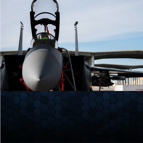
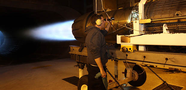
Testing and Evaluation
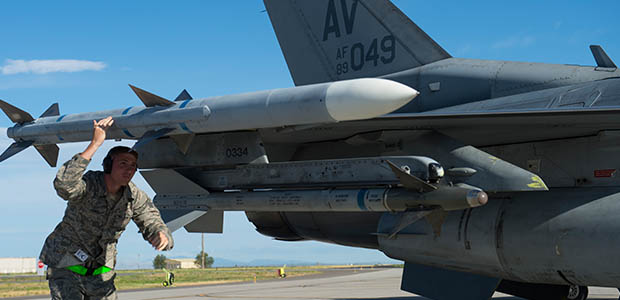
Between 2009 and 2019, the DOD Missile Defense Agency conducted 37% of its ballistic missile defense system flight tests as scheduled. IDA researchers conducted an independent assessment to identify causes for cancellations, delays and modifications and provided recommendations for improvement.
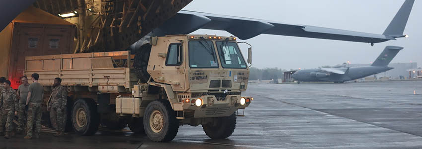
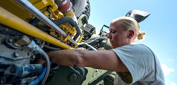
System Sustainment
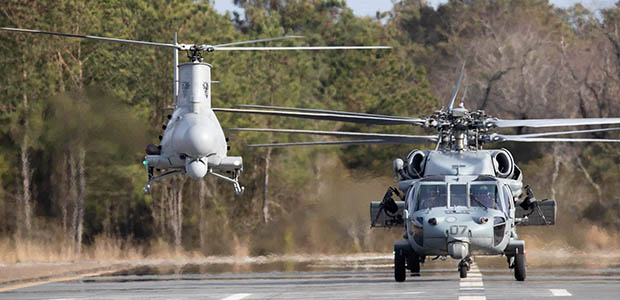
IDA has worked with military and civilian sponsors to construct end-to-end simulation models for maritime and aviation weapon systems and to investigate the strategic levers that drive readiness. In this conference presentation, we describe the complexities of properly emulating sustainment concepts and argue for the urgency of increased end-to-end modeling efforts in improving readiness across weapon systems.
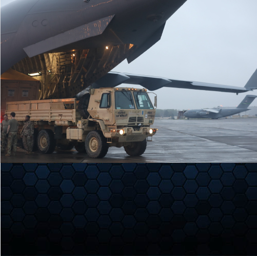
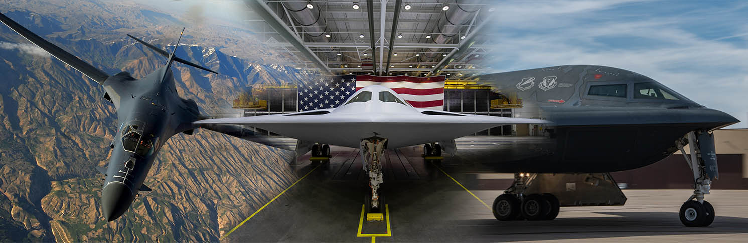
Assessing New Technologies and Weapon Systems
In 2024, IDA formed the Science, Systems and Sustainment Division (S3D), recognizing the need to continually evolve to meet the pressing needs of our government sponsors in the Department of Defense (DOD) and the Department of Homeland Security (DHS). IDA brought together talent from three divisions of the Systems and Analyses Center FFRDC to form the new division.
As weapon systems mature from the laboratory to the field, government leaders require expertise that crosses the full life cycle of weapon systems from basic science through test and evaluation (T&E) to operations, readiness and sustainment. S3D provides expertise over a broad range of portfolios to enable successful development, testing, fielding and sustainment of today’s weapon systems. Our methodological approaches vary across projects, but they include development of models and simulations; machine learning and statistical analyses; test design, analyses and reporting; and field exercises and operations.
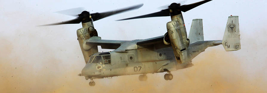
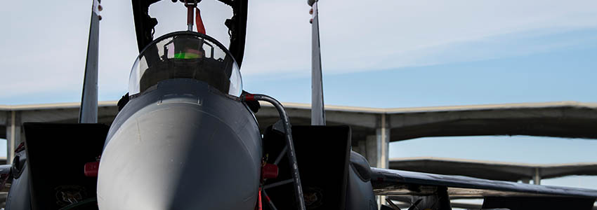
Systems: Concepts and Test
Systems: Missions, Operations and Evaluation